UART Serial Communication
BENEFIT
It’s the cheapest way to communicate between two devices. UART uses two lines to communicate. It requires a single wire for transmitting the data, Tx and another wire for receiving, Rx, making the hardware configuration easy and simple when compared with protocols such as SPI (serial peripheral interface) and USB (Universal Serial Bus) where four lines is required or allow multiple slaves to connect with, making them more expensive if you compare it with the UART communication.
DOWNSIDE
The drawback of the UART is that the speed for data transfer is low compared to SPI (serial peripheral interface) and USB (Universal Serial Bus).
Key Terms
Universal
The term “Universal” is attributed to the fact that both UARTs, the transmitting and receiving UARTs, are configurable to have the exact same packet format and transmission speeds (baud rate) to ensure a successful communication.
Asynchronous
The transmission of data between a transmitting UART to a receiving UART is not driven by a single source clock signal. If that were the case, it would be known as synchronous; the output of bits from the transmitting UART to the sampling of bits by the receiving UART would be synchronized.
To make sense of the data being transmitted, the sender and receiver agree on a set of rules, a protocol on how the data is packed, how many bits constitute a character, and when the data begins and ends.
To do so, the transmitting UART is configured to add a start and stop bits to the data frame being transferred, with an optional parity bit. This in turn becomes what is known as the packet format, as mentioned before. And it's readed by the receiving UART that has been configured in a similar fashion to allow the communication of both; knowing when to start or end the communication transfer.
BAUD RATE
The baud rate is defined as the rate of data transfer in serial communication.
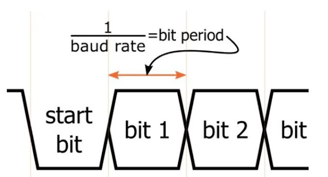
The Baud Rate describes the frequency, in regards to the time, required to transmit one bit of digital data. It’s expressed in bits per second, or bps.
For example, when you read a 9600-baud rate, it’s telling you that a bit can be transferred every 104.2 µs.
1/9600=104.2 us
The baud rate is the 2nd required configuration in both, the transmitter and receiver UARTs, for proper serial communication.
Packet
Packet is the term used to describe the block of bits that are structured in a specific format so both the transmitter and receiver UARTs can communicate through a serial transmission line.
This specific block of bits is called the data packet or packet format.
For the UART in specific the packet format is structured with 1 start bit, 5 to 9 data bits (depending on the UART), an optional parity bit, and 1 or 2 stop bits.
START BIT
The first bit of a one-byte UART data packet. The sending UART drives the data transmission line from high to low voltage when transfer of data needs to be initialized, for at least one bit duration. When the receiving UART detects the high to low voltage transition, it begins the transfer of the data frame, five to nine bits, at the frequency of the baud rate.
DATA FRAME
The actual data being transferred. It can be 5 bits up to 8 bits long if a parity bit is used. If no parity bit is used, the data frame can be 9 bits long.
PARITY
A single bit appended to the data frame for error detection purposes. Also known as the check bit.
The two types of error detection (parity check) are known as:
Even Parity − Here the total number of bits in the message is made even.
Odd Parity − Here the total number of bits in the message is made odd.
This parity bit is the one that could be set to either 1 or 0 to make the total number of 1-bits in the data frame either even ("even parity") or odd ("odd parity").
The sender, while creating the frame, it counts the numbers of 1s in it and adds the parity bit as follows:
For “even parity” check - If the number of 1s is even, parity bit value is 0. If the number of 1s is odd, parity bit value is 1.
For “odd parity” check - If number of 1s is odd, parity bit value is 0. If the number of 1s is even, parity bit value is 1.
The receiver end counts the number of 1s in it and
For “even parity” - if it’s even, the frame is accepted, otherwise it is rejected.
For “odd parity” - if it’s odd, the frame is accepted, otherwise it is rejected.
Note: this will check if there is a single error in the number, but won't work if there are two errors!
STOP BITS
The last bit of a one-byte UART data packet. It signals the receiving UART, the end of the transmitting data frame.
The sending UART drives the data transmission line from a low voltage to a high voltage for at least two bit durations to indicate there is no transmitting data.
As a summary:
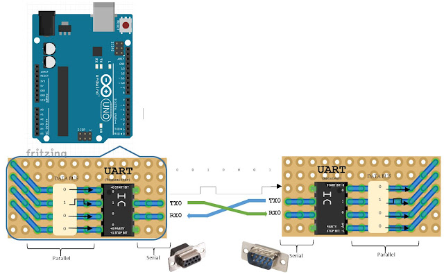
The UART communication is based on two UART devices connected directly with each other. Both have a transmission line, Tx and a receiving line, Rx. The only two wires to transmit data.
UART 1 - transmission line Tx pin - connect to -> UART 2 receiving line Rx pin.
UART 2 - transmission line Tx pin - connect to -> UART 1 receiving line Rx pin.
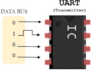
Parallel data is coming through the data bus to the universal asynchronous receiver-transmitter (UART) from a CPU, memory, or microcontroller.
The receiving UART takes the serial data, removes the start bit, a parity bit, and a stop bit, and converts the data back into parallel form to the data bus on the receiving end.


Comments