Posts

I2C - Real Time Clock (RTC) DS1307 - Write/Read

Image
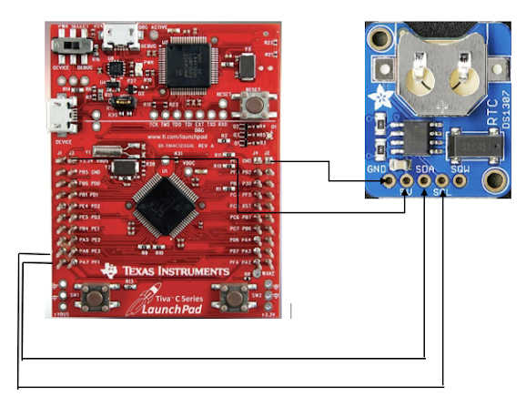
The following article walks you through a hands on exercise with a microcontroller and a real time clock IC to better understand and appreciate how the I2C Serial Communication Protocol is implemented. 

I2C Serial Protocol

Image
The following article will provide an overview of the I2C serial protocol. Please, take a look to the article “I2C - Real Time Clock (RTC) DS1307 - Write/Read” on my blog to see a practical approach using the Texas Instrument ARM base LaunchPad Evaluation Kit TM4C123G with a Real Time Clock (RTC) (DS1307) to interact with & better understand the I2C interface.  

UART programing in the TI ARM Tiva TM4C123G

Image
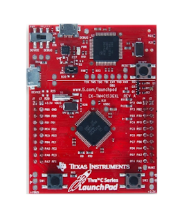
The aim of the following exercise is to show how to make use of an UART port in the ARM Cortex-M4-based microcontroller Tiva TM4C123G LaunchPad. The ASIC character “ Yes ” will be send to a terminal emulator program on your PC as an example.

UART Serial Communication

Image
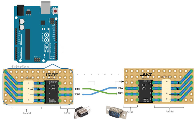
It’s a physical circuit integrated in a microcontroller, or a stand-alone IC, hardware interface that acts as a bridge between different devices such as a CPU, memory, or microcontroller. Is the port interface for serial communication. It performs parallel – to – serial data conversion at the transmitter side and serial – to – parallel data conversion at the receiver side.

Embedded C Programing w/ TM4C123G Microcontroller - 2.0 Functions, Macros & Header Files

Image
In our previous section,  Embedded C Programing w/ TM4C123G Microcontroller - 1.0 Register Addresses , it was discussed how to blink an LED by interacting directly with register addresses within the TM4C123G Microcontroller. A not very commune practice.  Here, we would like to simplify things by introducing Functions , Macros , and Header Files .  Function Currently, the code is a small program easily to interact. But eventually, it would become a little bit more challenging when adding more features. This means, more register addresses to manage.  Preliminary Code /* This program toggles the Green LED ON & OFF by using register addresses. The other LEDs (Red & Blue) can be configured as well. All LEDs are high active (a "1" turns ON the LED). PF1 - red LED PF2 - blue LED PF3 - green LED */ int main () { //Clock Gating Register *(( unsigned int *) 0x400FE608U ) = 0x20U ; //enable clock signal to GPIOF //GPIODIR Register *(( unsigned in